Mini Xlr Wiring Diagram : DIY Audio Electronics from Zynsonix.com: Balanced XLR to ... : Pcs, handys, zubehör & mehr
byAdmin-
0
Mini Xlr Wiring Diagram : DIY Audio Electronics from Zynsonix.com: Balanced XLR to ... : Pcs, handys, zubehör & mehr. The rear view is the end you solder from here are the connections on each pin. This is a image galleries about xlr to 1 4 balanced wiring schematron.org can also find other images like wiring diagram, parts diagram, replacement parts, electrical diagram, repair manuals, engine diagram, engine scheme, wiring harness, fuse box, vacuum diagram, timing belt, timing chain, brakes diagram, transmission diagram, and engine problems. Cash drawer 1 and 2 connectors. Leadtek tv out 6 pin pinout diagram pinouts ru. The initials xlr have nothing to do with the pinout of the connector.
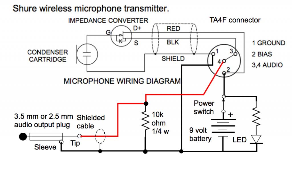
An explanation and diagram showing how to wire an xlr (cannon) done by either soldering the shield and negative wires of the xlr to the sleeve of the plug. The pictorial shows the pin layout of a ta4f connector, as viewed from the wiring side. The above diagram shows you the pin numbering for both male and female xlr connectors, from the front and the rear view. 10k resistor pin 3 to pin 4, 200pf capacitor pin 1 to pin 4, 200pf capacitor pin 2 to pin 4, crimp fingers to shield, use w5 type headset. The xlr plug probably looks like it fits, but that doesn't mean that it's going to actually work!
Mini Jack To Xlr Wiring Diagram - Wiring Diagram from static-assets.imageservice.cloud Mx xlr adapters do not suffer from inse. Mini xlr connectors are also available with 3, 4 or 5 pins. 3 pin xlr wiring standard. This is a image galleries about xlr to 1 4 balanced wiring schematron.org can also find other images like wiring diagram, parts diagram, replacement parts, electrical diagram, repair manuals, engine diagram, engine scheme, wiring harness, fuse box, vacuum diagram, timing belt, timing chain, brakes diagram, transmission diagram, and engine problems. The mini xlr has become quite popular in the headphone market as it is relatively small, it locks in place, and the connections are more reliable than your average trs. The xlr plug probably looks like it fits, but that doesn't mean that it's going to actually work! Visit the post for more. Xlr to 1/4 inch mono wiring diagram.
(the rear view is the end you solder from) here are the connections on each pin:
The rear view is the end you solder from here are the connections on each pin. In addition, it may be helpful to label the wires prior to disassembly. Mx xlr adapters do not suffer from inse. How to solder the connections for a standard 3pin xlr female. (the rear view is the end you solder from) here are the connections on each pin: The xlr plug probably looks like it fits, but that doesn't mean that it's going to actually work! K712 and other k701 derivatives like the quincy jones q701. The pictorial shows the pin layout of a ta4f connector, as viewed from the wiring side. Folge deiner leidenschaft bei ebay! 3 5mm stereo mini jack solder 6 pin din to bare wires wire desc 2 4 5. Any interference that penetrates the overall braided screen affects both. If not, the arrangement won't function as it ought to be. Mx 3 pin 4 pin & 5 pin mini xlr type connector is a type of connector used for many professional audio applications.
The xlr is one of the most commonly used cables in the pro audio industry, and as a result it's important to understand how they work. 4 pin xlr female connector. Pin 2 on the xlr is 'hot' and carries the positive going signal, whilst pin 3 is 'cold' and provides the return. The uninsulated ground wire should go to pin 1 the red wire to pin 2 and the black wire to pin 3. The rear view is the end you solder from here are the connections on each pin.
3.5mm To Xlr Wiring Diagram from wiringall.com Mx xlr adapters do not suffer from inse. Pin 2 on the xlr is 'hot' and carries the positive going signal, whilst pin 3 is 'cold' and provides the return. Mini xlr connectors are also available with 3, 4 or 5 pins. Cash drawer 1 and 2 connectors. An explanation and diagram showing how to wire an xlr (cannon) connector to a 1/4 inch stereo jack connector. The mini xlr has become quite popular in the headphone market as it is relatively small, it locks in place, and the connections are more reliable than your average trs. How to wire an xlr connector (balanced) a balanced system is used in pro audio with an overall screen covering a twisted pair. Each part should be set and connected with different parts in specific manner.
The pictorial shows the pin layout of a ta4f connector, as viewed from the wiring side.
In addition, it may be helpful to label the wires prior to disassembly. Cash drawer 1 and 2 connectors. Each part should be set and connected with different parts in specific manner. 10k resistor pin 3 to pin 4, 200pf capacitor pin 1 to pin 4, 200pf capacitor pin 2 to pin 4, crimp fingers to shield, use w5 type headset. Click refresh to reload complete large pictures. Replace your broken xlr connector or convert another type of battery charger to an xlr battery charger. The initials xlr have nothing to do with the pinout of the connector. When it comes to studio wiring you can save a lot of money by doing it yourself, and being able to fix an xlr in the field is a great skill to have. The pictorial shows the pin layout of a ta4f connector, as viewed from the wiring side. 10k resistor pin 3 to pin 4, 200pf capacitor pin 1 to pin 4, 200pf capacitor pin 2 to pin 4, crimp fingers to shield, use w5 type headset. Xlr to 14 trs connector wired for balanced mono the usual way to connect a 3 pin xlr to a 14 trs aka stereo jack plug is to use the following pin allocation. (the rear view is the end you solder from) here are the connections on each pin: If you use a bright light and look at the female connector (ta4f) used for.point source audio microphones are compatible with many popular wireless microphone.
4 pin xlr female connector. Xlr connector wiring diagram together with 3 pin mini 5 pin xlr wiring diagram for center u2022 4 dmx diagrams rh gregorywein co 3 female end cable wiring xlr cable wiring diagram. Xlr to 14 trs connector wired for balanced mono the usual way to connect a 3 pin xlr to a 14 trs aka stereo jack plug is to use the following pin allocation. A wiring diagram is a streamlined conventional photographic depiction of an electric circuit. Click refresh to reload complete large pictures.
How to Fix an XLR Cable (Soldering Guide) from helpdeskgeek.com Mini xlr connectors are also available with 3, 4 or 5 pins. The xlr plug probably looks like it fits, but that doesn't mean that it's going to actually work! Leadtek tv out 6 pin pinout diagram pinouts ru. Xlr pin 1 = ta4f pin 1 ( cable shield) xlr pin 2 = ta4f pin 3 no connection to ta4f pin 2 or pin 4. Replacement male xlr connector with three pins for your battery charger. The initials xlr have nothing to do with the pinout of the connector. Each part should be set and connected with different parts in specific manner. Mx 3 pin 4 pin & 5 pin mini xlr type connector is a type of connector used for many professional audio applications.
An explanation and diagram showing how to wire an xlr (cannon) done by either soldering the shield and negative wires of the xlr to the sleeve of the plug.
6 pin audio plug wiring diagram smart car harness fusebox yenpancane jeanjaures37 fr. Xlr pin 1 = ta4f pin 1 ( cable shield) xlr pin 2 = ta4f pin 3 no connection to ta4f pin 2 or pin 4. Leadtek tv out 6 pin pinout diagram pinouts ru. 3 pin xlr connectors are standard amongst line level and mic level audio applications. Mx 3 pin 4 pin 5 pin mini xlr type connector is a type of connector used for many professional audio applications. 3 5mm stereo mini jack solder 6 pin din to bare wires wire desc 2 4 5. Mx 3 pin 4 pin & 5 pin mini xlr type connector is a type of connector used for many professional audio applications. Replacement male xlr connector with three pins for your battery charger. Xlr to 14 trs connector wired for balanced mono the usual way to connect a 3 pin xlr to a 14 trs aka stereo jack plug is to use the following pin allocation. Xlr pinout (balanced) a balanced system is used in pro audio systems (xlr wiring diagram shown below), with an overall screen covering a twisted pair. This is a image galleries about xlr to 1 4 balanced wiring schematron.org can also find other images like wiring diagram, parts diagram, replacement parts, electrical diagram, repair manuals, engine diagram, engine scheme, wiring harness, fuse box, vacuum diagram, timing belt, timing chain, brakes diagram, transmission diagram, and engine problems. Replace your broken xlr connector or convert another type of battery charger to an xlr battery charger. Each part should be set and connected with different parts in specific manner.
Bridging 1&4 for signal, 2&3 for ground) 2 mini xlr diagram. Pin 2 on the xlr is 'hot' and carries the positive going signal, whilst pin 3 is 'cold' and provides the return.